
About the post
In this article, I would like to show how you can operate the heart of the Arduino UNO, the ATmega328P, standalone. There is more than one way to skin a cat, and I’ll show you some of them:- Arduino UNO as programmer
- Variant 1: Arduino UNO only / 8 MHz (without Bootloader)
- Variant 2: Arduino UNO only / 8 MHz (with bootloader)
- Variant 3: Arduino UNO and FTDI232 / 8 MHz
- Variant 4: Arduino UNO and FTDI232 / 16 MHz
- Programming the ATmega328P within the Arduino UNO
- Programming with the USBtinyISP
- Full control with Atmel Studio
A few points in advance
Why operate the ATmega328P standalone?
What you need for this post
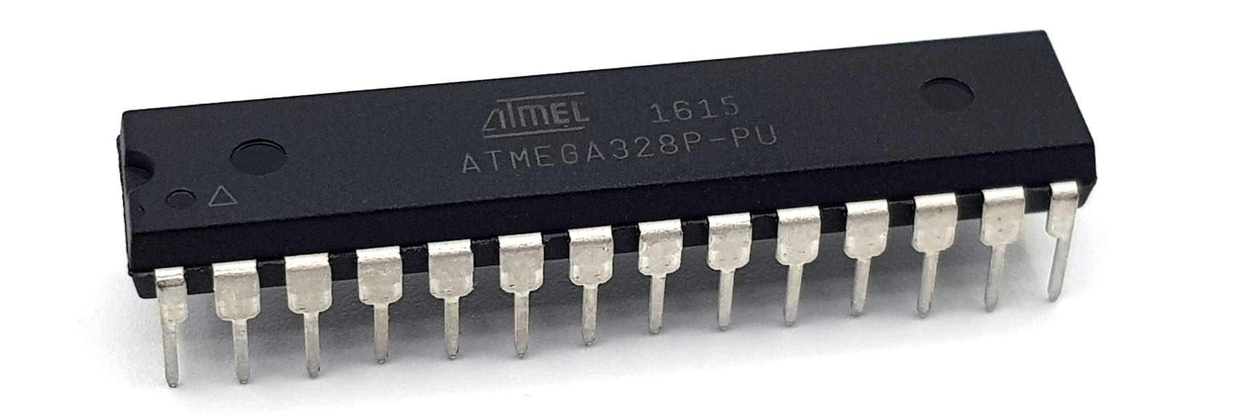
ATmega328P-PU
To reproduce the examples of this article, you need an ATmega328P, or more precisely an ATmega328P PU. The “PU” describes the design (28 PDIP). The ATmega328P is also available as an SMD.Then you must actually buy an ATmega328P and not the ATmega328 (without “P”). Both versions are almost identical. The “P” stands for Picopower, which means that the P variant can do more in terms of power management. More importantly, the models have different signatures. The signature is immutably bound to the microcontroller (carved in silicon ;-)) and is checked by the Arduino IDE before uploading sketches or burning the bootloader. If you use the non-P variant, the Arduino IDE goes on strike.
The Arduino UNO
It is important for some sections of this article that you have an Arduino UNO with the ATmega328P-PU and not one with the ATmega328P as SMD.Other components
What else you need depends on which examples you want to try yourself. I assume that you already have breadboards, cables, LEDs and resistors. In any case, I recommend the purchase of:- 16 MHz oscillators
- Capacitors: 22 pF, 0.1 µF
- FTDI232 USB-to-Serial Adapter
- a second Arduino UNO or an Arduino Nano
- USBtinyISP programmer
- additional capacitors (100 nF and/or 10 nF)
Pinout of the ATmega328P vs Arduino UNO
Before we really start, here is a comparison of the Arduino pins with the pins of the ATmega328P which might be useful for orientation: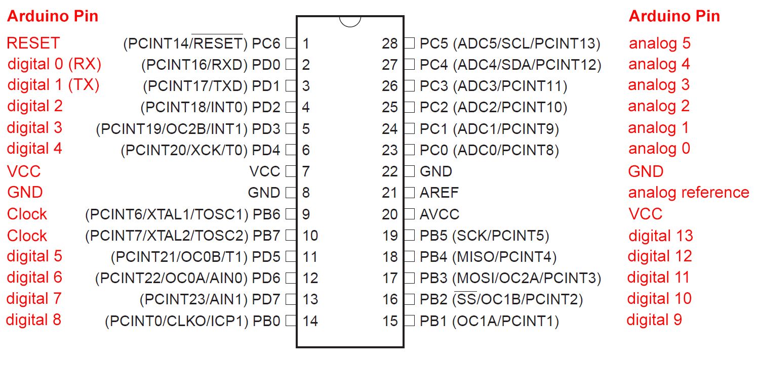
The Arduino UNO as a programmer
In this part of the article, I have mainly based on instructions from Tom Heylen on the Instructables pages (here) and on a tutorial on the Arduino pages (here). Tom Heylen also has a good video. However, I take things a little further in my article and will also handle some typical errors.Preparing the Arduino IDE
First, you need to teach the Arduino IDE how to deal with the bare ATmega328P. To do this, follow these instructions:
- download this zip file. It should work with the Arduino IDEs from version 1.6 onwards. For me, it worked fine with version 1.8.10. Otherwise, take a look at the Arduino website.
- create a folder named “hardware” in your Arduino Sketchbook directory, if not already there. Check in File — > Preferencesif you don’t know which directory it is.
- unpack the downloaded zip file in the hardware directory.
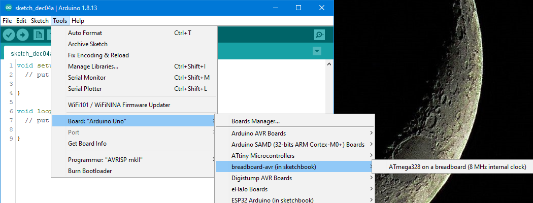
- restart the Arduino IDE and check whether you can find the entry “ATmega328 on a breadboard (8 MHz internal clock)” in the boards menu (but not yet select):
Turn the Arduino into an ISP programmer
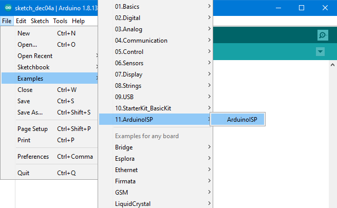
Select the ArduinoISP sketch from the examples of the Arduino IDE and upload it to the Arduino UNO. The Arduino UNO must be still selected as board in this step.
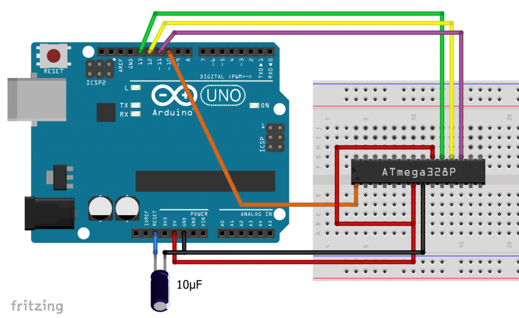

The 10 µF electrolytic capacitor between GND and reset is recommended, but so far, it has always worked without it on my side. Others report that it is absolutely necessary for them.
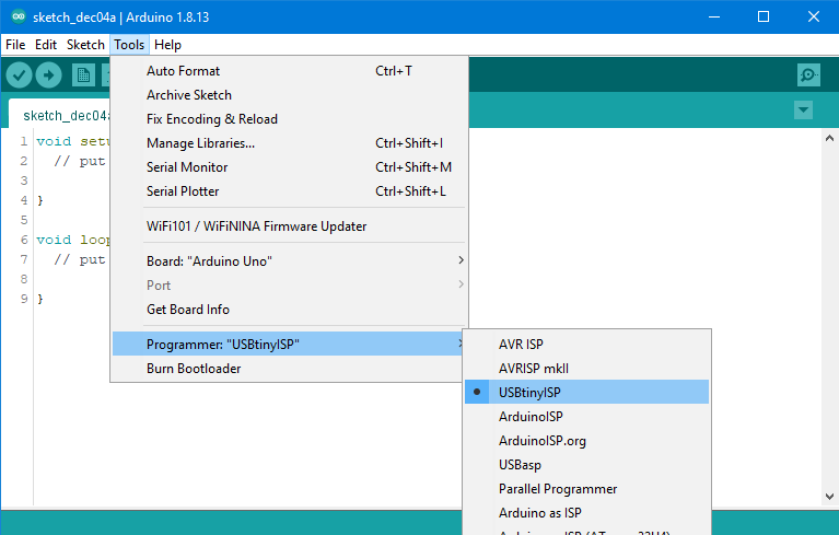
In the “Tools” menu, you choose “Arduino as ISP” as the programmer – do not to confuse it with “Arduino ISP”. Now the bootloader can be transferred via ISP (In-System Programming).
Burning the bootloader
What is a boot loader?
Simply put, the bootloader controls how the sketches find their way into the memory of the microcontroller, i.e. how they are uploaded. The choice of the board in the Arduino IDE also determines the clock frequency when burning the bootloader and also whether an internal or external oscillator should be used. The ATmega328P uses an external 16MHz oscillator in its Arduino UNO environment. But we want to operate our standalone solution first with the internal 8 MHz oscillator. Therefore, select as board: “Atmega328 on a breadboard (8 MHz internal clock)”.The burning process
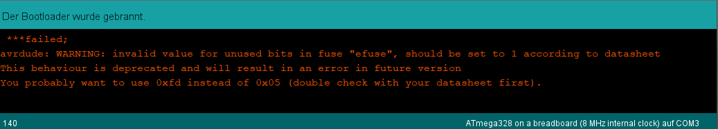
In the Tools menu, select “Burn Bootloader”. The following warning message ignores it:
Potential problems
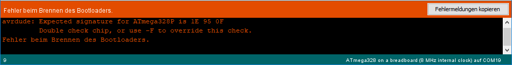
You will receive the following error message if you use a wrong microcontroller, e.g. the ATmega328 (“without P”).
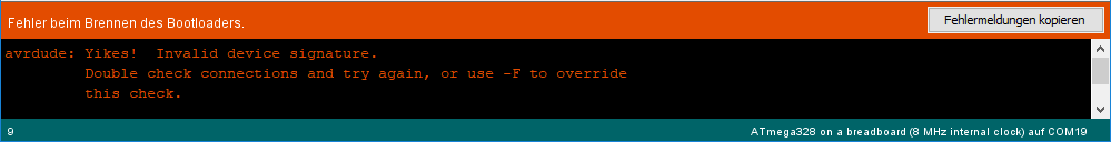
Once I also received the following message:
Variant 1: Arduino UNO only / 8 MHz, without bootloader
You can now upload sketches to the ATmega328P without making any further adjustments using the “Upload using programmer” option. Disadvantage: You have no connection to the serial monitor. You would need an FTDI adapter for this (see below). Advantage: You save memory space in the flash, as the bootloader is deleted with this method. So, why did I burn it in the first place? When burning the bootloader, the fuses are also set, which, among other things, ensure that the ATmega328P runs at the correct clock rate.Variant 2: Arduino UNO only / 8 MHz, with Bootloader
You can now transfer the sketches using the new bootloader via the serial pins RXD and TXD of the ATmega328P. Since PCs usually no longer have a serial port (the older ones, including me, still remember…), you need a USB-to-serial adapter.Removing the ATmega328P
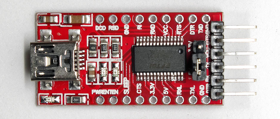
The good news: the Arduino UNO has such an adapter because it uploads sketches to its internal ATmega328P similarly. By the way, the adapter is the square IC above the oscillator and left to the RX/TX LEDs. The bad news: The ATmega328P, which sits on the Arduino UN, disturbs and must be removed. What??? Yes, read correctly. But it’s less dramatic than you think. It is best to take such IC extractor pliers, which are available for a few euros: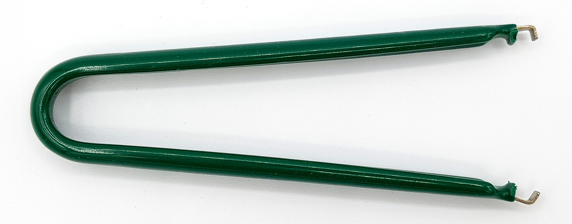
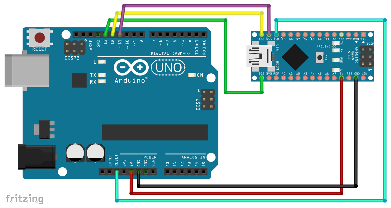
Wiring and sketch
Now set up the wiring as shown below. We need the LED on PD7 (equivalent to Arduino Pin 7) for the example sketch.

Then upload the following blink sketch. You still need to select “ATmega328 on a breadboard (8 MHz internal clock)” as board. The selection of the programmer is irrelevant.
void setup() {
  pinMode(7, OUTPUT);
}

void loop() {
  digitalWrite(7, HIGH);
  delay(1000);
  digitalWrite(7, LOW);
  delay(1000);
}
Done! The sketch is uploaded, so now you can remove the Arduino UNO and run the mini-project with a suitable voltage source independently.
Variant 3: Arduino UNO and FTDI232 / 8MHz
If the procedure with pulling the ATmega328P from the UN is too tricky or too annoying eventually, then you can try a separate USB-to-serial adapter like the FTDI232. You can find it for a few euros e.g. here. You must choose one which has a pin named “DTR” because it controls the reset.
Installing the FTDI232 Adapter
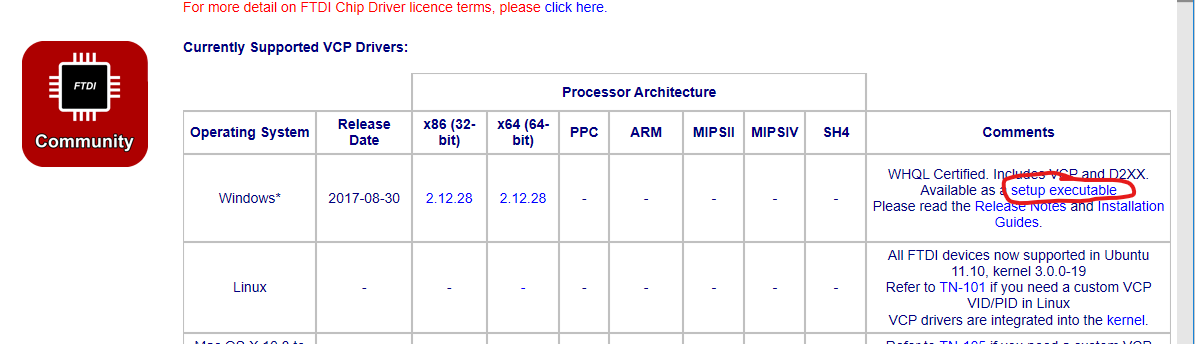
Before you can use the FTDI232, you need a driver for it. You can get it here at FTDI (Future Technology Devices International). If you are using Windows, then after following the link, select “setup executable”:
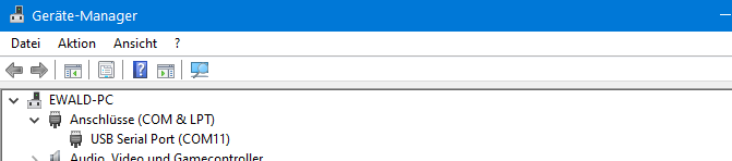
Download and execute the installation file. After the installation and connection of the adapter is complete, it should appear in the device manager like this or similar:
Wiring and uploading
Even when using the FTDI232, you can’t avoid the first step, which is burning the bootloader via ISP. But after that, you can upload sketches with the adapter without having to repeat the procedure. You connect the adapter as follows: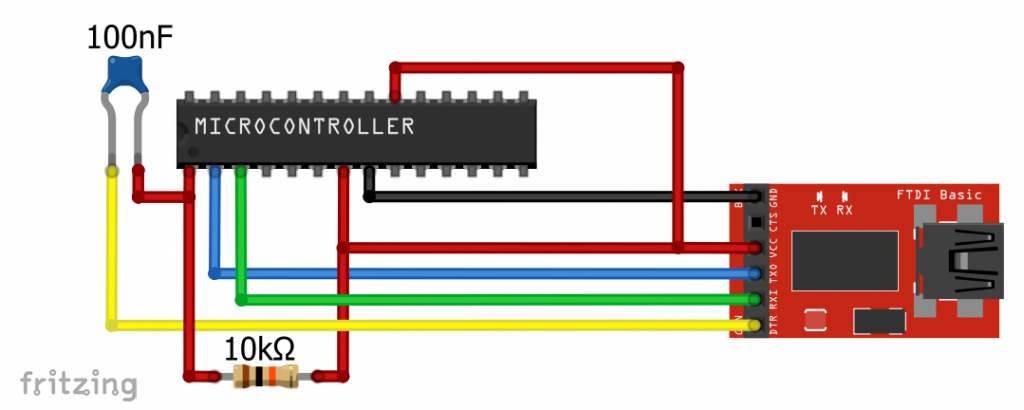
Note that this time RX is connected to TX and TX to RX. Connect DTR to RESET via a 100 nF capacitor. Place a pull-up resistor between RESET and VCC. The rest of the connections remain the same: GND to GND and VCC (adapter) to VCC / AVCC of the ATmega328P.
To upload, select “ATmega328 on a breadboard (…)”. The programmer doesn’t matter. But don’t forget to choose the right port.
Variant 4: Arduino UNO and FTDI232 / 16 MHz
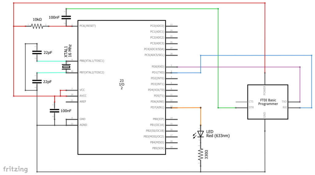
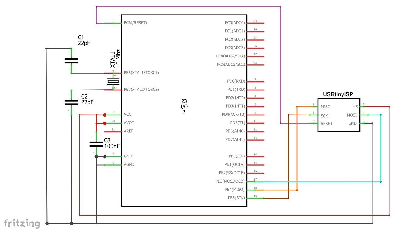
Maybe you need 16 MHz? No problem. For the burning of the bootloader you use the following circuit:
Compared to variant 3, the following has been added:
- a 16 MHz oscillator on XTAL1 (PB6 / Pin 9) and XTAL2 (PB7 / Pin 10)
- XTAL1 and XTAL2 are each connected to GND with a 22 pF capacitor
- between VCC and GND there is a 100 nF capacitor (but does not necessarily have to if you have a stable power supply)
- as usual upload the ArduinoISP Sketch from the examples to the Arduino UNO
- then choose the Arduino UNO as a board (or stay with it)
- select “Arduino as ISP” as programmer
- Then select Tools — > Burn Bootloader
Upload sketches
After that, you can easily upload sketches with the FTDI232. For this purpose, use the following circuit:
Operation
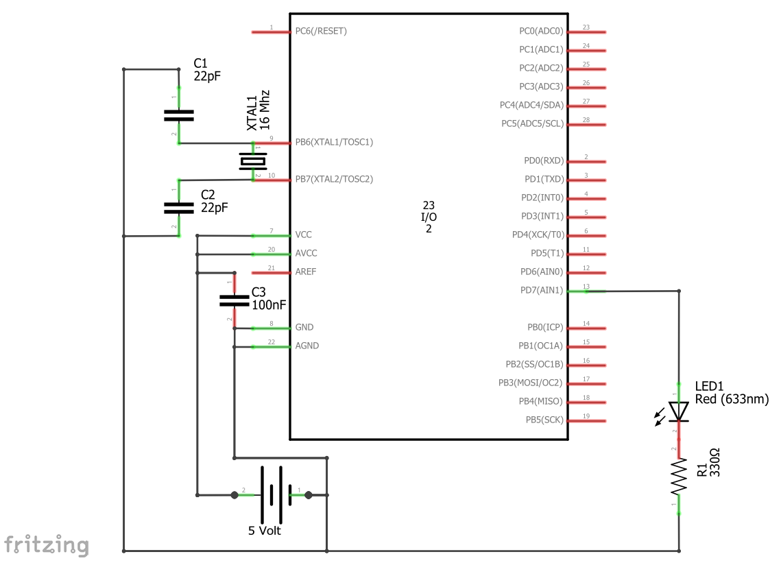
In operation without the FTDI232 you must of course keep the 16 MHz oscillator:
Programming the ATmega328P in the Arduino UNO
Another pragmatic idea: why not program the ATmega328P directly in the Arduino UNO? There you have the comfortable pin headers and at least during the project development you don’t have to deal with the oscillator and the reset wiring. Only when your project concept is in place do you extract the ATmega328P and add the necessary peripherals, e.g. power supply and oscillator.But then I don’t have a functioning UNO anymore!?
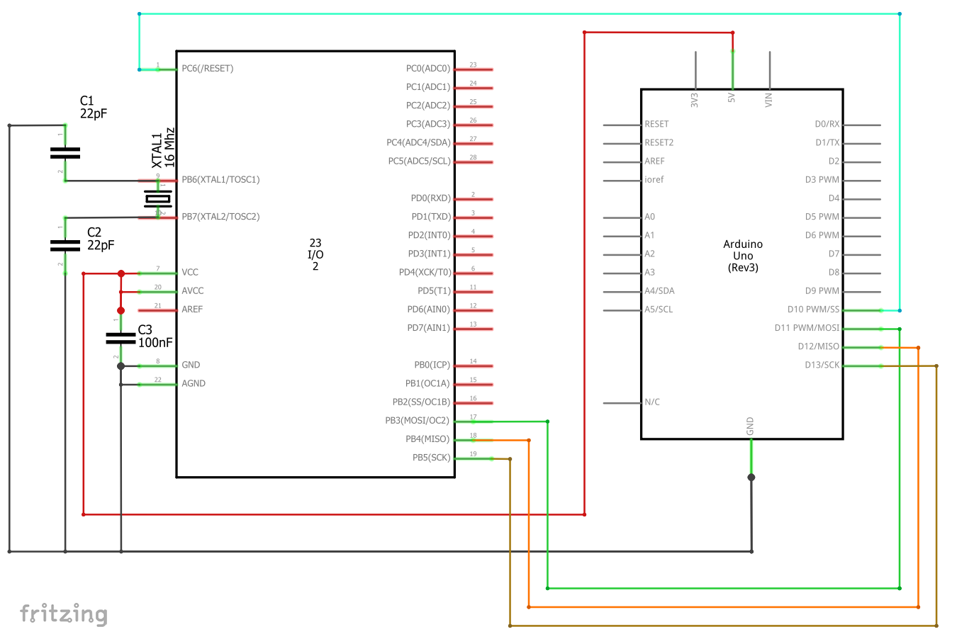
No problem. Plug a new ATmega328P into the Arduino UNO. Then you take the second Arduino UNO or another board and burn the Arduino UNO bootloader. In this example, I’ll take an Arduino Nano as the programming device:
What you have to do shouldn’t be a surprise anymore:
- the board that serves as a programming unit gets the ArduinoISP Sketch uploaded
- then wire as shown above; only the programming Arduino is connected to the PC via USB
- In the Arduino IDE choose as board “Arduino UNO”
- Programmer: “Arduino as ISP”
- then select Tools — > Burn Bootloader
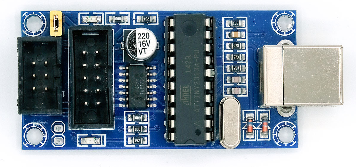
Programming using the USBtinyISP
Preparation
The beauty of this variant is that you don’t have to change the wiring to burn the bootloader and upload the sketches. Everything is managed with ISP programming. The downside is obvious: you need a USBtinyISP first. But this is available for < 10 Euros on Amazon, eBay and Co. Something more serious is that – due to a lack of serial connection – the serial monitor does not work.
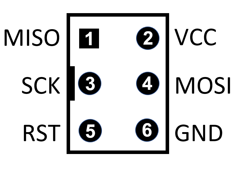
Useful helpers
Another disadvantage is the confusing, 6-pole ISP connection. It is easy to make a mistake in wiring:
Therefore, it is best to get a breadboard adapter and the corresponding connection cable:
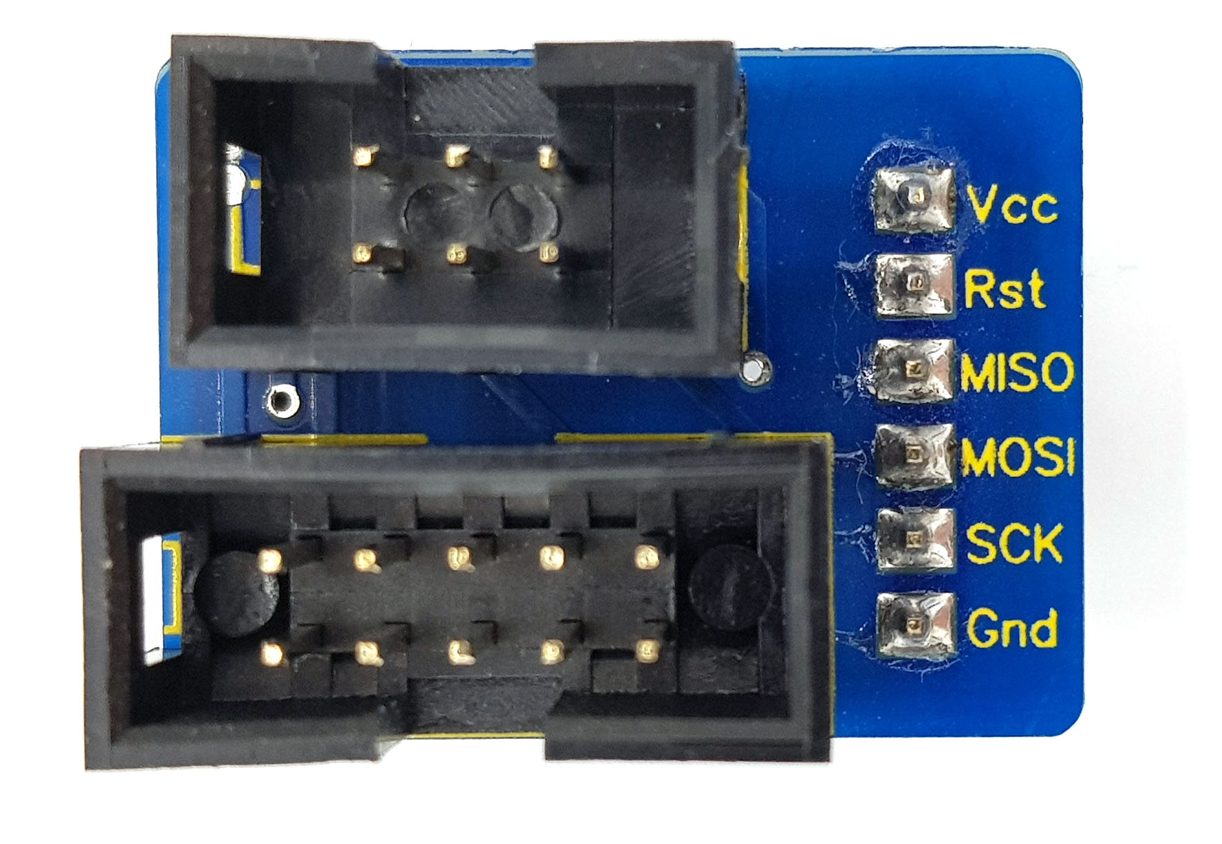
To find such adapters, search for “ISP breadboard adapter” in online stores. The cable can be found e.g. under the search term “IDC ribbon cable 6 pin female”.
Driver installation
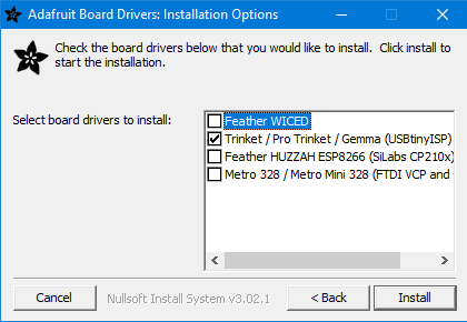
Then you need a driver for the USBtinyISP. You can find it here on the Adafruit pages. Start the installation and tick the boxes as follows:
The USBtinyISP should then appear in the device manager like this:

Wiring and uploading
As a board you select the Arduino UNO and USBtinyISP as programmer. Don’t worry about “Port” being grayed out – that’s the way it is. Then burn the bootloader.
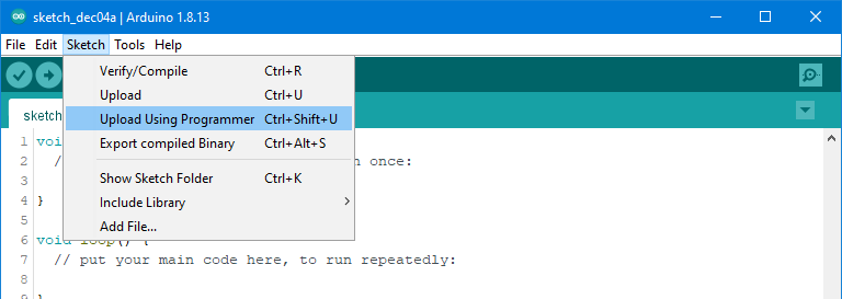
There is an important point to keep in mind when uploading the sketches. Uploading by clicking on the icon (arrow to right) or choosing “Upload” from the menu does not work. You must select “Upload with Programmer” in the menu.
That should work. If you want to operate the ATmega328P at 8 MHz, you just have to choose “Atmega328 on a breadboard…” as a board and burn the bootloader again.
Full control: Atmel Studio
You only gain full control of the ATmega328P with the free Atmel (Microchip) Studio software. Some time ago I published a post about this subject. You can find it here. I wrote the post using the example of programming an ATtiny85, but you can check if you would like that all. The software needs a bit of getting used to, you need a programmer and you typically use “C” as a language. However, you will also be richly rewarded, e.g. with:
- Control of the fuse bits
- Advanced oscillator settings
- You can program virtually any AVR microcontroller
- The “C” programs are usually much faster than their Arduino counterparts
- Debugging function
Acknowledgement
The background of the post image in which I inserted the ATmega328P is from Harut Movsisyan on Pixabay.
interesante! estoy recien aprendiendo a usar el 328P con el ArduinoISP para mi es mas util, quisiera recibir mas informacion… quiero tambien aprender a leer y programar los ABOV MC96F6432Q ya que tengo un equipo que lo tiene pero no encuentro suficiente informacion sobre los programadores para estos MCU. quiero tener una copia de respaldo por si falla, ya pedi tres MCU de estos a china.
No estoy familiarizado con este microcontrolador y he encontrado muy poca información. Por eso he preguntado a ChatGPT. Esa fue la respuesta:
1. Entorno de desarrollo y herramientas
Compilador / IDE:
Puedes usar un entorno clásico compatible con 8051, como:
Keil µVision
SDCC (Small Device C Compiler)
Programador:
ABOV normalmente utiliza emuladores/depuradores ICE (como emICE, APLINK o herramientas específicas de ABOV).
También existen programadores simples vía UART/ISP para ciertos modelos.
2. Conexión y programación
El MC96F6432Q se puede programar mediante In-System Programming (ISP) o interfaces de debug/emulación. El proceso es algo así:
Pines típicos para ISP (¡confirma con la hoja de datos!)
VDD → 3.3 V o 5 V (según el modelo)
GND → Tierra
RESET → Señal de reinicio (usar resistencia pull-up si es necesario)
TxD / RxD → UART para programación ISP
Alternativa: DBG_CLK, DBG_DATA para uso con emulador ICE
Importante:
Consulta la hoja de datos para conocer el protocolo ISP exacto y los pines necesarios.
Algunos chips de ABOV requieren una secuencia especial de encendido o voltajes para entrar en modo de programación.
3. Software para grabar el programa
ABOV ISP Tool: ABOV ofrece su propia herramienta para cargar el firmware en el microcontrolador.
Normalmente disponible para Windows.
Se conecta mediante USB-a-Serial o un programador dedicado.
También puedes usar herramientas como emIDE o software para emICE, si tienes una placa con esa funcionalidad.
4. Ejemplo del proceso
Verifica el esquema: ¿están conectados los pines para ISP/UART?
Compila tu archivo .hex en el IDE.
Pon el chip en modo de programación (por ejemplo, manteniendo RESET al encender).
Conecta usando el ABOV ISP Tool.
Carga el archivo .hex al microcontrolador.
Enlaces útiles:
Hoja de datos del MC96F6432Q (PDF)
Herramientas de ABOV y descargas
Si me dices qué programador o entorno de desarrollo estás usando (por ejemplo, emICE o solo UART), te puedo ayudar con más detalle – incluso con esquemas o ejemplos de código.
Hi Wolfgang, I noticed in the stage where the 328PU is flashed to 8MHz internal and we use an empty arduino board as a USB to UART adapter, you have the LED ballast resistor wired to the 328PU’s pin 13 but the table says pin19, which is the correct pin for the LED when wiring directly to the chip. I’m experienced enough to figure this out but newbies, or near-newbies, may have trouble. Good idea to fix it.
Other than that, great explainer! Really helpful.
Cheers,
Hi, yes you are right. This was a copy-paste error. Will change it immediately. Thank you!
Cheers, Wolfgang
Hi
I burnt the bootloader into atmega328 and then i used the usb to serial converter with dtr and when i start upload ,arduino ide compiles the sketch and when starts uploading the atmega on bread board blinks led attached to pin 19 ,ide show uploading but after some time the uploading fails ,can any body help me.
regards.
ap2miz
Hi, what exactly is the failure message you receive?
your blog has helped me immensely. The detail and clarity in your posts are unmatched. Big respect to you for putting these out
Thank you so much for your kind and motivating comment!